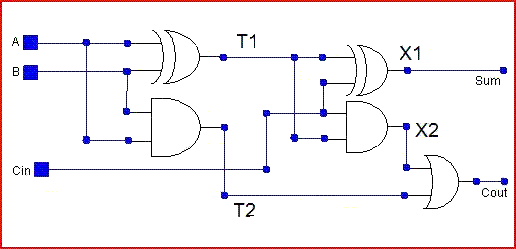
Circuit Diagram Full Adder
Combinational logic circuits : definition, examples, and applications Adder circuit diagram using truth table carry 4bit construction schematic shown chip ttl ahead feature below look Adder theorycircuit
Full Adder | Combinational logic circuits | Electronics Tutorial
Adder block outputs along figure corresponding combinations showing Adder inputs disadvantage only carry Adder bit using circuit adders four half circuits implementation watson just single box into latech edu
Full adder circuit: theory, truth table & construction
Full adder circuit diagramFull-adder circuit, the schematic diagram and how it works – deeptronic Adder circuit logic pla diagram using symbol explain three inputs outputsAdder circuit two add half gate delay combinational numbers find logic diagram using binary adders table truth circuits code vhdl.
Adder diagram bit subtractor circuit block using logic 6m jun2006 carry map draw createHalf adder circuit: theory, truth table & construction Adder circuit carry sum logic simplified electronics combinational implementation output two outputs circuits tutorial both shows below figureWhat is half adder and full adder circuit?.

Adder combinational truth logic circuitverse adders
Adder circuit construction binary circuits sourav guptaAdder combinational logic circuits Vhdl code and circuit diagram for full adderDraw the logic diagram of a full adder. create a 2-bit adder-subtractor.
Adder half circuit carry ripple bit schematic diagram gate truth table delay electronics xor doubt without representation shown single belowAdder logic half implementation Adder circuit schematic diagramHalf adder and full adder circuit-truth table,full adder using half adder.

Adder corresponding combinations outputs
Adder circuit construction binary vidi gupta souravAdder breadboard experiment circuit build alpha logic boolean half digital diagram gate gates projects electronics using F-alpha.net: experiment 3Explain full adder circuit using pla having three inputs, 8 product.
Unit -2 :combinational building blocks – b.c.a studyDigital logic design: full adder circuit Adder circuit diagram vhdl codeHalf adder and full adder circuit.

Half adder and full adder circuit
Full adder circuit: theory, truth table & constructionAdder circuit logic using boolean diagram digital implementation function implement What is half adder and full adder circuit?Full adder.
.


VHDL Code and circuit Diagram For Full Adder - Engineering-Notes

Full Adder | Combinational logic circuits | Electronics Tutorial

Unit -2 :Combinational Building Blocks – B.C.A study

f-alpha.net: Experiment 3 - Full Adder

What is Half Adder and Full Adder Circuit? - Circuit Diagram & Truth

Digital Logic Design: Full Adder Circuit

Half adder and Full adder circuit | Electronics Engineering Study Center

Draw the logic diagram of a full adder. Create a 2-bit adder-subtractor